Posts
Implementing Descriptor Tables
GDT, LDT & IDT Straight From The AMD64 Manual
On This Page
WARNING : From here onwards you need some experience with
x86_64assembly. I’ve done some reverse engineering stuffs so I have some basic knowledge to find my way out of this. You’ll need something similar! You must have knowledge of what are registers, how many registers are there in amd64 architecture, what are the uses of those registers, etc… Knowledge of more low level concepts will be a cherry on the top.
This page can be heavy on theory, but we actually need it. This is because I’ll be reading the amd64 architecture programmer’s manual and I’ll try to develop implementation code from there. This is fun because it feels like I’m actually getting a grasp of things and not just copy pasting code from somewhere. I’ve tried different posts on GDT and IDT but I feel like I’m missing some concept after reading them. I don’t understand why they did this and that. So, to overcome this, I plan to get to the problem’s root.
We now have a way to print a debug text on behalf of our kernel. We will be needing that in this part. We will be implementing a GDT (Global Descriptor Table) and IDT (Interrupt Descriptor Table) to handle interrupts. An interrupt is like a signal where a hardware component informs your CPU about some event that happened in outside world. Interrupts can be triggered by hardwares anytime actually but usually this happens when you hit something on your keyboard, or move your mouse (or scroll fingers on touchpad). There can be an interrupt to handle signals sent by a timer attached to your PC that sends interrupt signals after say every 5 seconds. Your CPU then uses the IDT to jump to a function that whose address and usage is predefined in the IDT. This function then handles that interrupt signal. What’s GDT? It’s for the context switch. By context switch I mean jumping from currently running code to the interrupt handler. The code changes suddenly, for this we have the GDT.
To understand GDT you first need knowledge of what is memory segmentation. In easy words, memory segmentation is dividing system memory into different segments (parts) depending on usage. There is different segment code running program and different segemnt for data used by running program. When program is running code from a particular code segment, an offset to that segment will be stored in the cs (code segment) register. Similary, when program is accessing data from a data segment, an offset to that segment will be stored the ds (data segment) register. You just need to get an idea of this concept for now as this concept is now superseded by paging.
By table here, we mean actual tables! We will create a struct with fields as columns and have an array (or list) of these structs to act as rows. Here I’ll take some paragraphs from amd64 manual volume 2.
Segmentation
The legacy x86 architecture supports a segment-translation mechanism that allows system software to relocate and isolate instructions and data anywhere in the virtual-memory space. A segment is a contiguous block of memory within the linear address space. The size and location of a segment within the linear address space is arbitrary. Instructions and data can be assigned to one or more memory segments, each with its own protection characteristics. The processor hardware enforces the rules dictating whether one segment can access another segment.
The segmentation mechanism provides ten segment registers, each of which defines a single segment. Six of these registers (CS, DS, ES, FS, GS, and SS) define user segments. User segments hold software, data, and the stack and can be used by both application software and system software. The remaining four segment registers (GDT, LDT, IDT, and TR) define system segments. System segments contain data structures initialized and used only by system software. Segment registers contain a base address pointing to the starting location of a segment, a limit defining the segment size, and attributes defining the segment-protection characteristics. Check The Rings Of Privilege
In long mode, the effects of segmentation depend on whether the processor is running in compatibility mode or 64-bit mode:
- In compatibility mode, segmentation functions just as it does in legacy mode, using legacy 16-bit or 32-bit protected mode semantics.
- 64-bit mode, segmentation is disabled, creating a flat 64-bit virtual-address space. As will be seen, certain functions of some segment registers, particularly the system-segment registers, continue to be used in 64-bit mode.
The segment base is the lowest address in a given segment, and is equal to the segment selector * 16 (lshift by 4 bits). The POP and MOV instructions can be used to load a new segment selector into one of the segment registers. When this occurs, the selector is updated and the segment base is set to selector * 16. The segment limit and segment attributes are unchanged, but are normally 64K (the maximum allowable limit) and read/write data, respectively
Segmentation Data Structures & Registers
Segment Descriptors — As the name implies, a segment descriptor describes a segment, including its location in virtual-address space, its size, protection characteristics, and other attributes.
Descriptor Tables - Segment descriptors are stored in memory in one of three tables. The Global Descriptor Table (
GDT) holds segment descriptors that can be shared among all tasks. Multiple local-descriptor tables (LDT) can be defined to hold descriptors that are used by specific tasks and are not shared globally. The Interrupt Descriptor Table (IDT) holds gate descriptors that are used to access the segments where interrupt handlers are located.Task-State Segment - A task-state segment (
TSS) is a special type of system segment that contains task-state information and data structures for each task. For example, aTSSholds a copy of theGPRs andEFLAGSregister when a task is suspended. A TSS also holds the pointers to privileged software stacks.Segment Selectors - Descriptors are selected for use from the descriptor tables using a segment selector. A segment selector contains an index into either the
GDTorLDT.

Below figure will show different registers used by different segmentation mechanism.

These registers have the following relationship to the data structures.
Segment Registers - The six segment registers (
CS,DS,ES,FS,GS, andSS) are used to point to the user segments. A segment selector selects a descriptor when it is loaded into one of the segment registers. This causes the processor to automatically load the selected descriptor into a software-invisible portion of the segment register.Descriptor-Table Registers - The three descriptor-table registers (
GDTR,LDTR, andIDTR) are used to point to the system segments. The descriptor-table registers identify the virtual-memory location and size of the descriptor tables.Task Register (TR) - Describes the location and limit of the current task state segment (
TSS).

Selector format consists for following fields :
Selector Index (SI) Field - Bits 15:3. The selector-index field specifies an entry in the descriptor table. Descriptor-table entries are eight bytes long, so the selector index is scaled by 8 to form a byte offset into the descriptor table. The offset is then added to either the global or local descriptor-table base address (as indicated by the table-index bit) to form the descriptor-entry address in virtual-address space.
Table Indicator (TI) Bit - Bit 2. The
TIbit indicates which table holds the descriptor referenced by the selector index. WhenTI= 0 theGDTis used and whenTI=1 theLDTis used. The descriptor-table base address is read from the appropriate descriptor-table register and added to the scaled selector index as described above.Requestor Privilege-Level (RPL) Field - Bits 1:0 (2 bits). The
RPLrepresents the current privilege level (CPL) the processor is operating under at the time the selector is created. This relates to The Rings of Privilege.Null Selector - Null selectors have a selector index of 0 and
TI= 0, corresponding to the first entry in theGDT. However, null selectors do not reference the firstGDTentry but are instead used to invalidate unused segment registers. A general-protection exception (#GP) occurs if a reference is made to use a segment register containing a null selector in non-64-bit mode. By initializing unused segment registers with null selectors software can trap references to unused segments. Null selectors can only be loaded into theDS,ES,FSandGSdata-segment registers, and into theLDTRdescriptor-table register. A#GPoccurs if software attempts to load theCSregister with a null selector or if software attempts to load theSSregister with a null selector in non 64-bit mode or atCPL= 3.
Segment Registers
Six 16-bit segment registers are provided for referencing up to six segments at one time. All software tasks require segment selectors to be loaded in the CS and SS registers. Use of the DS, ES, FS, and GS segments is optional, but nearly all software accesses data and therefore requires a selector in the DS register.

The processor maintains a hidden portion of the segment register in addition to the selector value loaded by software. This hidden portion contains the values found in the descriptor-table entry referenced by the segment selector. The processor loads the descriptor-table entry into the hidden portion when the segment register is loaded. By keeping the corresponding descriptor-table entry in hardware, performance is optimized for the majority of memory references.

Figure above shows the format of the visible and hidden portions of the segment register. Except for the FS and GS segment base, software cannot directly read or write the hidden portion (shown as gray shaded boxes).
CSRegister - TheCSregister contains the segment selector referencing the current code-segment descriptor entry. All instruction fetches reference theCSdescriptor. When a new selector is loaded into theCSregister, the current-privilege level (CPL) of the processor is set to that of the CS-segment descriptor-privilege level (DPL). So, descriptors have their own privilege level.Data-Segment Registers - The
DSregister contains the segment selector referencing the default data-segment descriptor entry. TheSSregister contains the stack-segment selector. TheES,FS, andGSregisters are optionally loaded with segment selectors referencing other data segments. Data accesses default to referencing theDSdescriptor except in the following two cases:- The
ESdescriptor is referenced for string-instruction destinations. - The
SSdescriptor is referenced for stack operations.
- The
Segment Registers In 64-Bit Mode
CSRegister in 64-Bit Mode - In 64-bit mode, most of the hidden portion of theCSregister is ignored. Only the L (long), D (default operation size), and DPL (descriptor privilege-level) attributes are recognized by 64-bit mode. Address calculations assume aCS.basevalue of 0.CSreferences do not check theCS.limitvalue, but instead check that the effective address is in canonical form.DS,ES, andSSRegisters in 64-Bit Mode - In 64-bit mode, the contents of theES,DS, andSSsegment registers are ignored. All fields (base, limit, and attribute) in the hidden portion of the segment registers are ignored. Address calculations in 64-bit mode that reference theES,DS, orSSsegments are treated as if the segment base is 0. Instead of performing limit checks, the processor checks that all virtual-address references are in canonical form. Neither enabling and activating long mode nor switching between 64-bit and compatibility modes changes the contents of the visible or hidden portions of the segment registers. These registers remain unchanged during 64-bit mode execution unless explicit segment loads are performed.FSandGSRegisters in 64-Bit Mode - Unlike theCS,DS,ES, andSSsegments, theFSandGSsegment overrides can be used in 64-bit mode. WhenFSandGSsegment overrides are used in 64-bit mode, their respective base addresses are used in the effective-address (EA) calculation. The completeEAcalculation then becomesFS.baseorGS.base+ base + (scale * index) + displacement. TheFS.baseandGS.basevalues are also expanded to the full 64-bit virtual-address size, as shown in figure below. Any overflow in the 64-bit linear address calculation is ignored and the resulting address instead wraps around to the other end of the address space.

Descriptor Tables
Descriptor tables are used by the segmentation mechanism when protected mode is enabled (CR0.PE=1). These tables hold descriptor entries that describe the location, size, and privilege attributes of a segment. All memory references in protected mode access a descriptor-table entry. As previously mentioned, there are three types of descriptor tables supported by the x86 segmentation mechanism:
- Global descriptor table (
GDT) - Local descriptor table (
LDT) - Interrupt descriptor table (
IDT)
Software establishes the location of a descriptor table in memory by initializing its corresponding descriptor-table register.
Global Descriptor Table
The GDT contains code-segment and data-segment descriptor entries (user segments) for segments that can be shared by all tasks. In addition to the user segments, the GDT can also hold gate descriptors and other system-segment descriptors. System software can store the GDT anywhere in memory and should protect the segment containing the GDT from non-privileged software.
Segment selectors point to the GDT when the table-index (TI) bit in the selector is cleared to 0. The selector index portion of the segment selector references a specific entry in the GDT. The first entry in GDT is the null selector and selecting it causes general-protection exception (#GP). The
first usable GDT entry is referenced with a selector index of 1.

Global Descriptor Table Register (GDTR)
The global descriptor-table register (GDTR) points to the location of the GDT in memory and defines its size. This register is loaded from memory using the LGDT instruction.

GDTR for legacy modes
GDTR for long modesOur bootloader boots us into 64-bit mode (subset of long mode). So, in our kernel, this pointer will be represented by a struct like this
#include <stdint.h>

// struct to represent gdtr in code
typedef struct{
    uint16_t table_limit;
    uint64_t table_base_address;
} gdt_pointer_t __attribute__((packed));
Meaning of these fields is given below :
Limit - 2 bytes. These bits define the 16-bit limit, or size, of the
GDTin bytes. The limit value is added to the base address to yield the ending byte address of the GDT. A general-protection exception (#GP) occurs if software attempts to access a descriptor beyond the GDT limit. The offsets into the descriptor tables are not extended by the AMD64 architecture in support of long mode. Therefore, theGDTRandIDTRlimit-field sizes are unchanged from the legacy sizes. The processor does check the limits in long mode duringGDTandIDTaccesses.Base Address - 8 bytes. The base-address field holds the starting byte address of the
GDTin virtual-memory space. TheGDTcan be located at any byte address in virtual memory, but system software should align theGDTon a quad-word boundary to avoid the potential performance penalties associated with accessing unaligned data.
The AMD64 architecture increases the base-address field of the GDTR to 64 bits so that system software running in long mode can locate the GDT anywhere in the 64-bit virtual-address space. The processor ignores the high-order 4 bytes of base address when running in legacy mode.
Local Descriptor Table
Protected-mode system software can optionally create a local descriptor table (LDT) to hold segment descriptors belonging to a single task or even multiple tasks. The LDT typically contains code-segment and data-segment descriptors as well as gate descriptors referenced by the specified task. Like the GDT, system software can store the LDT anywhere in memory and should protect the segment containing the LDT from non-privileged software.
Segment selectors point to the LDT when the table-index bit (TI) in the selector is set to 1. The selector index portion of the segment selector references a specific entry in the LDT. Unlike the GDT, however, a selector index of 0 references the first entry in the LDT (when TI = 1, the selector is not a null selector)
LDTs are described by system-segment descriptor entries located in the GDT, and a GDT can contain multiple LDT descriptors. The LDT system-segment descriptor defines the location, size, and privilege rights for the LDT. Loading a null selector into the LDTR is useful if software does not use an LDT. This causes a #GP if an erroneous reference is made to the LDT.

LDT and GDTLocal Descriptor Table Register (LDTR)
The local descriptor-table register (LDTR) points to the location of the LDT in memory, defines its size, and specifies its attributes. The LDTR has two portions. A visible portion holds the LDT selector, and a hidden portion holds the LDT descriptor. When the LDT selector is loaded into the LDTR, the processor automatically loads the LDT descriptor from the GDT into the hidden portion of the LDTR.

LDTR in legcay modes
LDTR in long modesIn code, the LDTR register will be implemented something like this :
#include <stdint.h>

// representation of ldtr in code
typedef struct {
    uint16_t selector;
    uint16_t descriptor_attributes;
    uint32_t table_limit;
    uint64_t table_base_address;
} ldt_pointer_t __attribute__((packed));
Here is the explanation of these fields :
- LDT Selector - 2 bytes. These bits are loaded explicitly from the
TSS(task segment selector) during a task switch, or by using theLLDT(Load Local Descriptor Table) instruction. TheLDTselector must point to anLDTsystem-segment descriptor entry in theGDT. If it does not, a general-protection exception (#GP) occurs.
The following three fields are loaded automatically from the LDT descriptor in the GDT as a result of loading the LDT selector.
Base Address - The base-address field holds the starting byte address of the
LDTin virtual-memory space. Like theGDT, theLDTcan be located anywhere in system memory, but software should align theLDTon a quad-word boundary to avoid performance penalties associated with accessing unaligned data. The AMD64 architecture expands the base-address field of theLDTRto 64 bits so that system software running in long mode can locate anLDTanywhere in the 64-bit virtual-address space. The processor ignores the high-order 32 base-address bits when running in legacy modeLimit - This field defines the limit, or size, of the
LDTin bytes. TheLDTlimit as stored in theLDTRis 32 bits. When theLDTlimit is loaded from theGDTdescriptor entry, the 20-bit limit field in the descriptor is expanded to 32 bits and scaled based on the value of the descriptor granularity (G) bit. G-bit is 0 if limit field is not scaled (no calculation needs to be performed to get the actual size). G-bit is set to 0 if limit field is scaled by 4KBi. In this case the limit field then equals the number of 4KB blocks available in the segment.
If an attempt is made to access a descriptor beyond the LDT limit, a general-protection exception (#GP) occurs.
- Attributes - This field holds the descriptor attributes, such as privilege rights, segment presence and segment granularity.
Interrupt Descriptor Table
The final type of descriptor table is the interrupt descriptor table (IDT). Multiple IDTs can be maintained by system software. System software selects a specific IDT by loading the interrupt descriptor table register (IDTR) with a pointer to the IDT. As with the GDT and LDT, system software can store the IDT anywhere in memory and should protect the segment containing the IDT from non-privileged software.
The IDT can contain only the following types of gate descriptors:
- Interrupt gates
- Trap gates
- Task gates.
IDT entries are selected using the interrupt vector number rather than a selector value. The interrupt vector number is scaled by the interrupt-descriptor entry size to form an offset into the IDT. The interrupt-descriptor entry size depends on the processor operating mode as follows :
- In long mode, interrupt descriptor-table entries are 16 bytes.
- In legacy mode, interrupt descriptor-table entries are eight bytes.

Interrupt Descriptor Table Register (IDTR)
The interrupt descriptor-table register (IDTR) points to the IDT in memory and defines its size. This register is loaded from memory using the LIDT instruction. The format of the IDTR is identical to that of the GDTR in all modes.
Legacy Segment Descriptors
Segment descriptors define, protect, and isolate segments from each other. There are two basic types of descriptors, each of which are used to describe different segment (or gate) types:
- User Segments - These include code segments and data segments. Stack segments are a type of data segment.
- System Segments - System segments consist of
LDTsegments and task-state segments (TSS). Gate descriptors are another type of system-segment descriptor. Rather than describing segments, gate descriptors point to program entry points.
Figure below shows the generic format for user-segment and system-segment descriptors. User and system segments are differentiated using the S bit. S = 1 indicates a user segment, and S = 0 indicates a system segment. Gray shading indicates the field or bit is reserved.

Using this, we can implement a representation in our code like this :
#include <stdint.h>

// implementation of a general segment descriptor
typedef struct {
    // segment limit is divided into 2 parts
    // fist part is bit 0 to 15 in first dword
    // second pat is bit 16 to 19 in second dword
    uint16_t segment_limit_low;

    // base address is divided into 3 parts
    // first part is bit 16 to 31 in first dword
    // second part is bit 0 to 7 in second dword
    // third and final part is from bit 24 to 32 in second dword
    uint16_t base_address_low;
    uint8_t base_address_middle;

    // bit 0 to 3 is for type field
    // bit 4 is S bit (user segment or system segment)
    // bits 5 and 6 make up the DPL (descriptor privilege level) field
    // bit 7 is P bit (present bit)
    uint8_t access_flags;

    // this field contains the higher 4 bits of segment limit (bits 0:3)
    // then there is the AVL Bit (bit 4)
    // then a reserved bit (bit 5)
    // then a D/B bit (bit 6)
    // and at last the Granularity (G) bit (bit 7)
    uint8_t attributes;

    // finally the higher part of base_address
    uint8_t base_address_high;
} generic_segmnet_descriptor_t __attribute__((packed));
Explanation of all these fields :
- Segment Limit - The 20-bit segment limit is formed by concatenating bits 19:16 of the upper doubleword with bits 15:0 of lower doubleword. The segment limit defines the segment size, in bytes. The granularity (G) bit controls how the segment-limit field is scaled.
- Base Address - The 32-bit base address is formed by concatenating bits 31:24 of the upper doubleword with bits 7:0 of the same doubleword and bits 15:0 of the lower doubleword. The segment-base address field locates the start of a segment in virtual-address space.
- S Bit and Type Field - Bit 12 and bits 11:8 of the upper doubleword. The S and Type fields, together, specify the descriptor type and its access characteristics.
- Descriptor Privilege-Level (DPL) Field - Bits 14:13 of the upper doubleword. The DPL field indicates the descriptor-privilege level of the segment. DPL can be set to any value from 0 to 3, with 0 specifying the most privilege and 3 the least privilege.
- Present (P) Bit - Bit 15 of the upper doubleword. The segment-present bit indicates that the segment referenced by the descriptor is loaded in memory. If a reference is made to a descriptor entry when P = 0, a segment-not-present exception (#NP) occurs. This bit is set and cleared by system software and is never altered by the processor.
- Available To Software (AVL) Bit - Bit 20 of the upper doubleword. This field is available to software, which can write any value to it. The processor does not set or clear this field.
- Default Operand Size (D/B) Bit - Bit 22 of the upper doubleword. The default operand-size bit is found in code-segment and data-segment descriptors but not in system-segment descriptors. Setting this bit to 1 indicates a 32-bit default operand size, and clearing it to 0 indicates a 16-bit default size. The effect this bit has on a segment depends on the segment-descriptor type.
- Granularity (G) Bit - Bit 23 of the upper doubleword. The granularity bit specifies how the segment-limit field is scaled. Clearing the G bit to 0 indicates that the limit field is not scaled. In this case, the limit equals the number of bytes available in the segment. Setting the G bit to 1 indicates that the limit field is scaled by 4 Kbytes (4096 bytes). Here, the limit field equals the number of 4-Kbyte blocks available in the segment. Setting a limit of 0 indicates a 1-byte segment limit when G = 0. Setting the same limit of 0 when G = 1 indicates a segment limit of 4095.
- Reserved Bits - Generally, software should clear all reserved bits to 0, so they can be defined in future revisions to the AMD64 architecture.
Code Segment Descriptors
If you’re confused whether this is a new thing or not? Let me explain it this way : generic segment descriptors what we saw above was the general layout of any descriptor and this code segment descriptor is a subset (more like a special case) of generic segment descriptors. Notice what we have in place of S-bit and Type field!

Above figure shows the code-segment descriptor format (gray shading indicates the bit is reserved). All software tasks require that a segment selector, referencing a valid code-segment descriptor, is loaded into the CS register. Code segments establish the processor operating mode and execution privilegelevel. The segments generally contain only instructions and are execute-only, or execute and readonly. Software cannot write into a segment whose selector references a code-segment descriptor.
Code-segment descriptors have the S bit set to 1, identifying the segments as user segments. Type-field bit 11 differentiates code-segment descriptors (bit 11 set to 1) from data-segment descriptors (bit 11 cleared to 0). The remaining type-field bits (10:8) define the access characteristics for the codesegment, as follows:
Conforming (C) Bit - Bit 10 of the upper doubleword. Setting this bit to 1 identifies the code segment as conforming. When control is transferred to a higher-privilege conforming code-segment (C = 1) from a lower-privilege code segment, the processor
CPLdoes not change. Transfers to non-conforming code-segments (C = 0) with a higher privilege-level than the CPL can occur only through gate descriiptors.Readable (R) Bit - Bit 9 of the upper doubleword. Setting this bit to 1 indicates the code segment is both executable and readable as data. When this bit is cleared to 0, the code segment is executable, but attempts to read data from the code segment cause a general-protection exception (
#GP) to occur.Accessed (A) Bit - Bit 8 of the upper doubleword. The accessed bit is set to 1 by the processor when the descriptor is copied from the
GDTorLDTinto theCSregister. This bit is only cleared by software.

- Code-Segment Default-Operand Size (D) Bit - Bit 22 of byte +4. In code-segment descriptors, the D bit selects the default operand size and address sizes. In legacy mode, when D=0 the default operand size and address size is 16 bits and when D = 1 the default operand size and address size is 32 bits. Instruction prefixes can be used to override the operand size or address size, or both.
Got an idea of how the structure of Code Segment Descriptor will look like? Think before reading further. It’ll look same as the generic one. Just the manipulation of type filed will change and S bit will always be set to 1!
Data Segment Descriptors
Again notice the structure of data segment descriptor (below) is similar to generic segment descriptor. Only the type field changed.

Above figure shows the data-segment descriptor format. Data segments contain non-executable information and can be accessed as read-only or read/write. They are referenced using the DS, ES, FS, GS, or SS data-segment registers. The DS data-segment register holds the segment selector for the default data segment. The ES, FS and GS data-segment registers hold segment selectors for additional data segments usable by the current software task.
The stack segment is a special form of data-segment register. It is referenced using the SS segment register and must be read/write. When loading the SS register, the processor requires that the selector reference a valid, writable data-segment descriptor.
Data-segment descriptors have the S bit set to 1, identifying them as user segments. Type-field bit 11 differentiates data-segment descriptors (bit 11 cleared to 0) from code-segment descriptors (bit 11 set to 1). The remaining type-field bits (10:8) define the data-segment access characteristics, as follows:
Expand-Down (E) Bit - Bit 10 of the upper doubleword. Setting this bit to 1 identifies the data segment as expand-down. In expand-down segments, the segment limit defines the lower segment boundary while the base is the upper boundary. Valid segment offsets in expand-down segments lie in the byte range limit+1 to
0xFFFFor0xFFFFFFFF, depending on the value of the data segment default operand size (D/B) bit. Expand-down segments are useful for stacks, which grow in the downward direction as elements are pushed onto the stack. The stack pointer, ESP, is decremented by an amount equal to the operand size as a result of executing a PUSH instruction. Clearing the E bit to 0 identifies the data segment as expand-up. Valid segment offsets in expand-up segments lie in the byte range 0 to segment limit.Writable (W) Bit - Bit 9 of the upper doubleword. Setting this bit to 1 identifies the data segment as read/write. When this bit is cleared to 0, the segment is read-only. A general-protection exception (
#GP) occurs if software attempts to write into a data segment when W = 0.Accessed (A) Bit - Bit 8 of the upper doubleword. The accessed bit is set to 1 by the processor when the descriptor is copied from the
GDTorLDTinto one of the data-segment registers or the stacksegment register. This bit is only cleared by software.

- Data-Segment Default Operand Size (D/B) Bit - Bit 22 of the upper doubleword. For expand-down data segments (E=1), setting D=1 sets the upper bound of the segment at
0xFFFFFFFF(32 bit operand size). Clearing D=0 sets the upper bound of the segment at0xFFFF(16 bit operand size).
In the case where a data segment is referenced by the stack selector (SS), the D bit is referred to as the B bit. For stack segments, the B bit sets the default stack size. Setting B=1 establishes a 32-bit stack referenced by the 32-bit ESP register. Clearing B=0 establishes a 16-bit stack referenced by the 16-bit SP register.
System Descriptors
There are two general types of system descriptors: system-segment descriptors and gate descriptors. System-segment descriptors are used to describe the LDT and TSS segments. Gate descriptors do not describe segments, but instead hold pointers to code-segment descriptors. Gate descriptors are used for protected-mode control transfers between less-privileged and more-privileged software. System-segment descriptors have the S bit cleared to 0. The type field is used to differentiate the various LDT, TSS, and gate descriptors from one another.

Below you can see format of LDT and TSS descriptor in legacy and compatibility modes.

Gate Descriptors
Gate descriptors hold pointers to code segments and are used to control access between code segments with different privilege levels. There are four types of gate descriptors:
- Call Gates - These gates are located in the
GDTorLDTand are used to control access between code segments in the same task or in different tasks.

- Interrupt Gates and Trap Gates - These gates are located in the
IDTand are used to control access to interrupt-service routines.

- Task Gates - These gates are used to control access between different tasks. They are also used to transfer control to interrupt-service routines if those routines are themselves a separate task.

And here is their implementation in code :
#include <stdint.h>

// implementation of call gate descriptor
typdef struct {
    uint16_t target_code_segment_offset_low;
    uint16_t target_code_segment_selector;

    // only lower nibble is for parameter count
    // higher nibble is reserved
    uint8_t parameter_count;

    // access flags
    // similar in generic segment descriptor
    // S bit is off here
    uint8_t access;

    uint16_t target_code_segment_offset_high;
} call_gate_descriptor_t __attribute__((packed));

// implementation of interrupt gate descriptor and trap gate descriptor
typdef struct {
    uint16_t target_code_segment_offset_low;
    uint16_t target_code_segment_selector;
    uint8_t reserved;

    // access flags
    // similar in generic segment descriptor
    // S bit is off here
    uint8_t access;

    uint16_t target_code_segment_offset_high;
} interrupt_gate_descriptor_t __attribute__((packed));

// implementation of task gate descriptor
typdef struct {
    uint16_t reserved1;
    uint16_t tss_selector;
    uint8_t reserved2;

    // access flags
    // similar in generic segment descriptor
    // S bit is off here
    uint8_t access;

    uint16_t reserved3;
} task_gate_descriptor_t __attribute__((packed));
Long Mode Segment Descriptors
Code Segment Descriptor In Long Mode
Structure of code segment descriptor in long mode is given below. In place of reserved bit, a new field is added : The L-Bit. This decides whether the program is running in 64-bit (L = 1) mode or compatibility mode (L = 0). The only valid setting for D bit is D = 0 (in long mode). Setting D = 1 & L = 1 is reserved for future useui.

Data Segment Descriptor In Long Mode
Almost everything is ignored here.

System Segment Descriptor Types In Long Mode
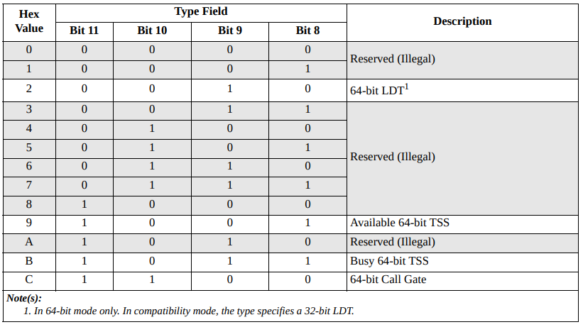

In 64-bit mode, the LDT and TSS system-segment descriptors are expanded by 64 bits as show below.

Implementing this one is easy, now that we’ve done a few already :
#include <stdint.h>

// implementation of system segment descriptor
typedef struct {
    uint16_t segment_limit_low;


    // base address divided into 4 parts now
    uint16_t base_address_0;
    uint8_t base_address_1;

    // access flags
    uint8_t access;

    // contains higher nibble of segment limit
    // avl bit, a reserved field and the granularity bit
    uint8_t attributes;

    uint8_t base_address_2;
    uint32_t base_address_3;

    // bits 8 to 12 are 0
    uint32_t reserved;
} system_segment_descriptor_t __attribute__((packed));
Gate Descriptors
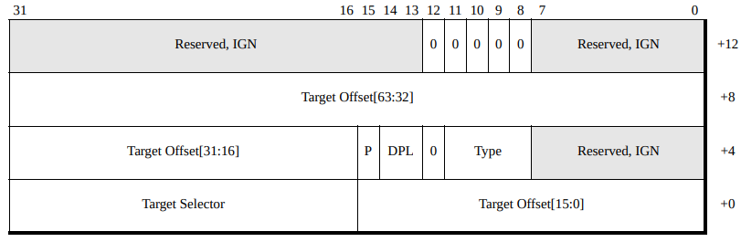

These can also be done easily. I’m too tired to do it here. Next we will be installing GDT and IDT in our kernel.